Centrifuge Piping System
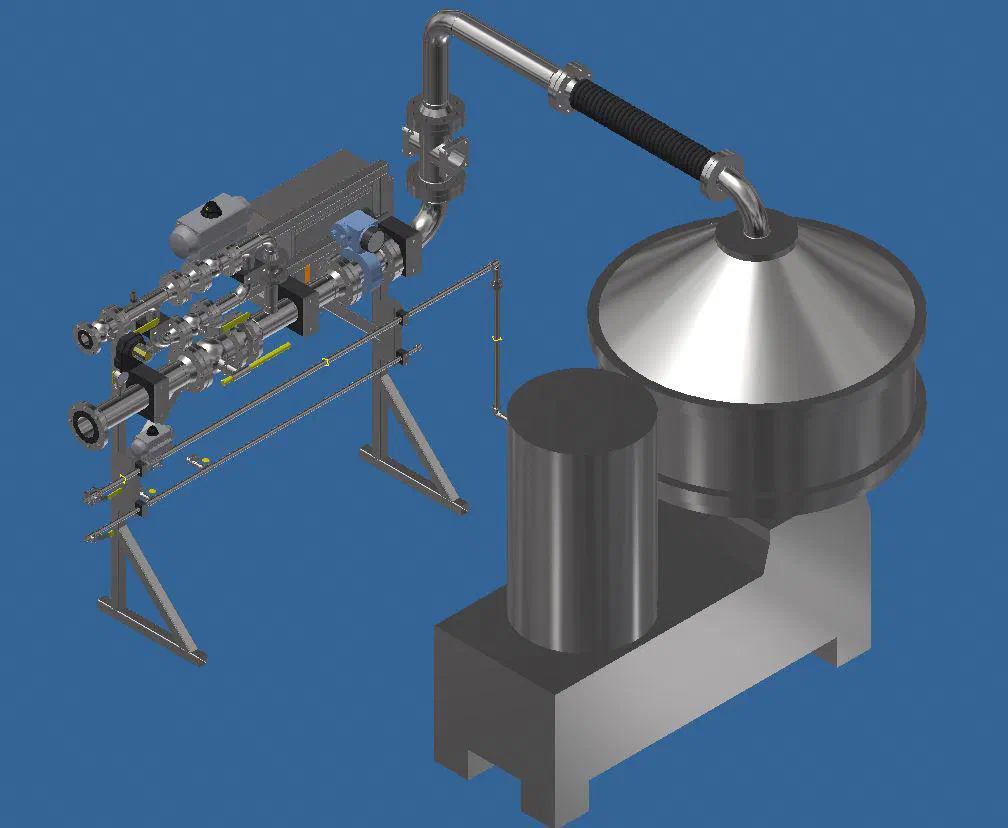
A valve and instrument manifold on its own stand, piped into a customer's centrifuge.
- Employer
- Hart Mechanical
- Role
- Mechanical Design Engineer
- Industry
- Industrial processing
- Period
- 2017 to 2018
- Scale
- Valve and instrument manifold piped into a centrifuge on a base frame
What it is
This is a valve and instrument manifold on its own stand, piped into a centrifuge mounted on a base frame. Hart designed and built the piping and supporting steel. The customer handled the process side, so I wasn’t involved in what the centrifuge was separating.
The design
Like the arsenic removal skid, this was a case of someone else specifying the process equipment and what had to connect to what, and our job being to turn that into something that could be fabricated, installed, operated, and maintained. That meant routing the connections the process required, keeping valves and instruments where a person could reach them, supporting the pipework so it carried itself instead of hanging off the equipment, and making sure the centrifuge could be serviced without cutting out any pipe.
I modeled and rendered the full assembly in SolidWorks for review before it went to our shop.
Specific skills
- SolidWorks
- process piping layout around vendor equipment
- valve and instrument manifold arrangement
- support stand design
- 3D modelling and rendering
- collaboration with in-house machine and weld shops